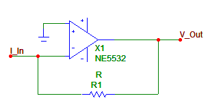
Case 1 : Textbook Opamp
This is the usual way to do it. Most CDPs have this. It sounds bad, of course. Input current has steps which will put the opamp's slew rate to the test. During these spikes, the input stage will have to handle large offsets which is a Bad Thing. Some have noticed that a faster opamp yields better sound, which seems logical.
By the way, the opamp is labeled "NE5532" here as this is the first model I happened to grab in my library while making these figures. This is not what I would use ! (even if this opamp is found in commercial players, yikes !)
A better solution is to get rid of the opamp.

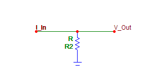
Case 2 : Resistor a la Audio Note.
Many have noticed how much better this sounds. There is a drawback though : the DAC output is not at its ideal voltage ; instead it fluctuates according to the signal. This causes distortion, because the DAC output voltage compliance is small.
And it is unusable for TDA1545, because this DAC wants its output held at 2/3 of its powersupply voltage.

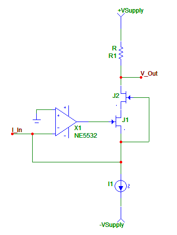
Case 3 : Folded Cascode (credits to Rudolf Broertjes).
It takes a little moment to realize the opamp is out of the signal path here. The JFET is used as a cascode ; the opamp drives it so as to maintain its source to the reference voltage (0V here). A current source (I1) provides bias. Output voltage appears on the resistor.
The opamp is out of the signal path because it can only influence the signal through coupling of the opamp output via the JFET's parasitic cap or the DAC's output voltage compliance, or by consuming current at its input. The opamp output voltage is NOT directly connected to the output as in Case 1 above !
We should, therefore, select an opamp with low input current (JFET or FET input), and high speed. I chose the AD825, as I liked its sound in other applications.
Interestingly, I was thinking about a schematic exactly like this one when suddenly Rudolf Broertjes posted his on the TNT mailing list. So he gets the credits for faster thinking !

Case 4 : Enhanced Folded Cascode.
JFETs have a parasitic capacitance which varies with Vds. I did not feel this was a good thing here as this is directly coupled to the signal. So I added this cascoded JFET to suppress the effect (a la Borbely). It works very well.
Main drawback is that the signal is referenced to V+, just like the previous cascode stage. So V+ has to be connected to the amp GND, directly or via some capacitor. This is quite annoying.

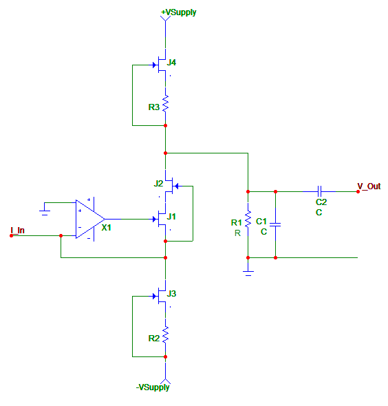
Case 5 : Final Schematic concept
Adding another current source for bias allows us to connect the output resistor to the ground as it should be. We are free to choose whatever resistance value we want provided the bias sources are set so that the idle voltage on this resistor does not saturate the JFETs or the upper current source.
Basically, V_Out = (I2-I1+I_In) * R
This is very simple and elegant. The output is simply capacitively coupled to my preamp.

Case 6 : Final Schematic implementation
Here we see the actual bias sources/sinks and output lowpass filter (just a first order filter, nothing fancy really).