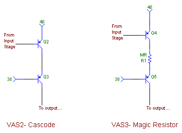
Fig. 5-1 : VAS Variations
It has been remarked that the VAS is important in amplifier sound quality. This backs the memory theory, as its contribution to memory effects is huge. How can a single transistor be so critical ? Simply, it is at the same time the main gain stage and the one that heats the most (it takes the full output swing). And, its errors are multiplied by its gain.
For once, I will not have a funky circuit here, and we will simply try to put a Cascode on the VAS.

Fig. 5-1 : VAS Variations |
We will build a model amplifier around this VAS, make it output a full swing of -30/+30V, and plot the linearity (upper plot) and dissipated power in the gain transistor (lower plot). Blue is for Standard and red is for Cascode.

Fig. 5-2 : VAS Linearity and Power |
This is old news, but the Cascoded version is much more linear (the gain curve is flatter). See Douglas Self's Power Amplifier Design Handbook for details. As for the power, of course the Cascode version has much more constant dissipation. The current does not vary very much actually, as the impedance that the VAS has to feed is quite high, being only the current source collector, and a buffer transistor's base.
Cascoded VAS's are used almost everywhere, and they are a good step towards reducing memory. However, it might be possible to do a even a little bit better.

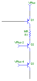
Fig. 5-3 : The Magic Resistor |
We have a constant voltage v around the gain transistor (Q2/4), enforced by the cascode (Q3/5). However, the current i varies, even if by a small quantity. The Power p is not constant. Let Vo be the v without the Magic Resistor. then,
v = Vo - R*i
p = v i = (Vo - R i) i = Vo i - R i^2
Those who remember their algebra (?) will note that, if we choose R = Vo/(2I), then at the DC bias point, little variations of i only affect p at the second order : power variations are therefore much smaller.
Tricky thing is, the emmiter resistor of the both transistors is part of R, so we can't use the above formula straight away ; a simulation will do nicely. VAS Transistor is BC560C, Cascode is BF470 :

Fig. 5-4 : The Magic Resistor at work Power dissipated in the gain transistor versus output voltage. |
This set of curves is the power in the gain transistor versus amplifier output voltage, with the resistor stepped. 50 Ohms seems nice, as it gives an almost constant power. It works !
There should be no stability issues. Just in case, I put the resistor on the collector side, because the C-B paratitic cap is smaller than the E-B one.
Now, for a simulation of the complete amplifier. With the VAS as the only source of memory, the global memory goes from 4.56 to 0.4. This is interesting, but it still swamps the memory of the input stage. Careful examination reveals the cause to be the thermal Vbe variations of the cascode transistor, which are enough to vary the voltage across the gain transistor. The Magic resistor can do nothing here.
What shall we do then... Well, obviously ;-)

Fig. 5-5 : The Cascoded Cascode |
Now, it is getting serious : VAS memory is down to 0.004, and can be made to go as low as 0.002 with the magic resistor in place. The last part of the circuit that needs exercising is the current mirror :
| Current Mirror | Memory |
| Perfect | 0.01 |
| Realistic | 0.03 |
This can be taken care of easily by changing the emitter resistor in the current mirror for 1k instead of 100 Ohms. This gets us back to the value of a perfect current mirror.
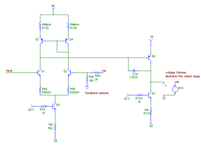
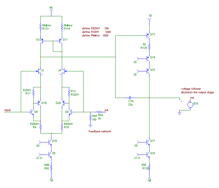
We have taken a rather standard amplifier topology (Fig. 5-6) and transformed into a rather unusual one (Fig. 5-7), while reducing memory at least a 500-fold. Now is the time for a listening test !

Fig. 5-6 : Before |

Fig. 5-7 : After |
On to the next part ! Listening tests !