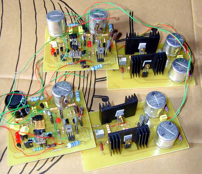
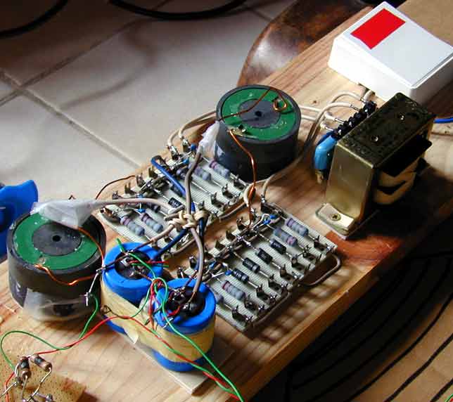
The complete prototype (2 channels). Pay attention to the numerous filtering caps (4700uF each) and the number of components that are socketed. LEDs provide low-noise bias for the input stage tail source, and also 1.8V voltage steps for Cascodes.
Signal stages are on the left, and the output stage boards (right) are connected to them via a socket soldered below the board.
(Background, courtesy of Ikea lighting fixtures inc.)
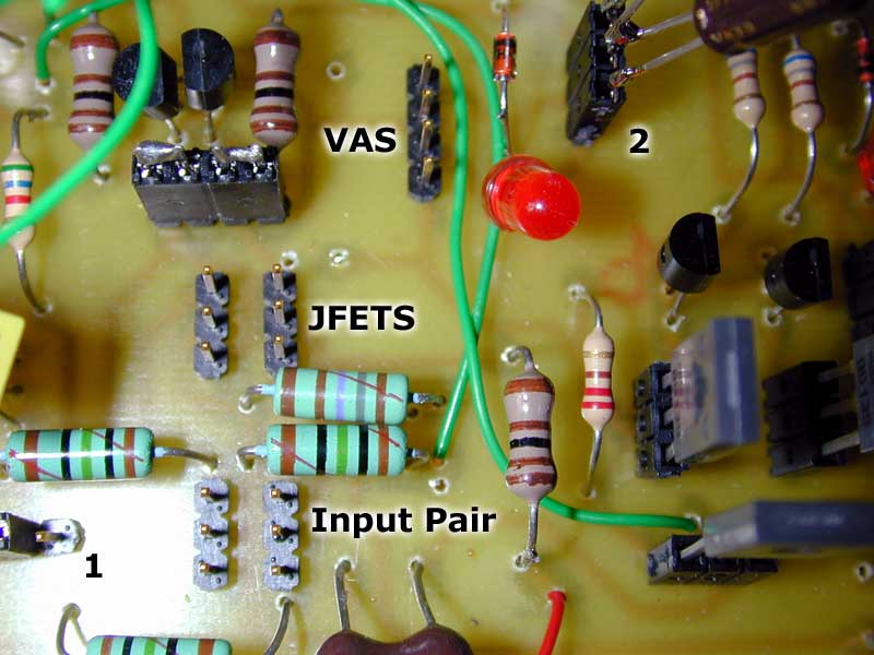
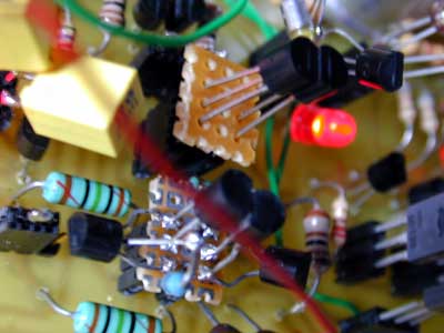
A closeup of the input stage, with transistors removed. Notice the pins sticking out, these are for quick exchange of small modules (see below). The textx on the picture mean :
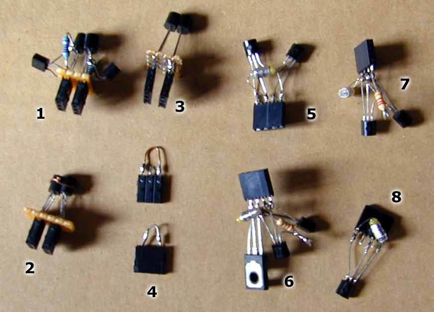
Below are the pluggable modules :
All VAS'ses have their compensation caps soldered very close (130 pF Styroflex).
A closeup on the input stage ; here we see the New input stage (CFP+JFETS). The CFP is the lower module, the JFET pair is at the left of the glowing LED.
The Power Supply.
Rectifier bridge has Schottky diodes, resostors and caps to absorb switching noise. Chokes for filtering (salvaged from a loudspeaker crossover). With them I no longer hear the noise of the fridge starting...
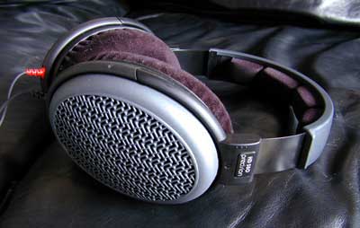
The test speakers.
Did you expect it to be able to drive normal speakers ? HD580, Z=300 Ohms. Headphone listening helps pinpoint the amp faults more easily than in-room listening with speakers, IMHO. Besides, these sound gorgeous.
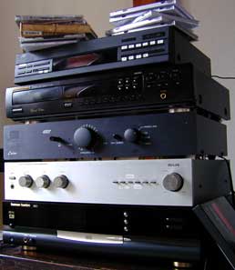
The Stereo.
From top to bottom : some cds, a bad sounding JVC tuner, a CD63SE, a Cairn amp, a Philips amp for the tweeters, a Harman Kardon DVD1...
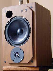
The real speakers.
Marantz Monitors that I found in a dumpster with destroyed drivers. First I only changed the drivers ; some years later I re-made the crossover to match the new drivers. I bi-amplify because I was too lazy to adjust the tweeter level with resistors. They sound quite good, they are definitely not the weak point in my system (it is the amplifier).